Design Description
Mechanical Design: “Bones”
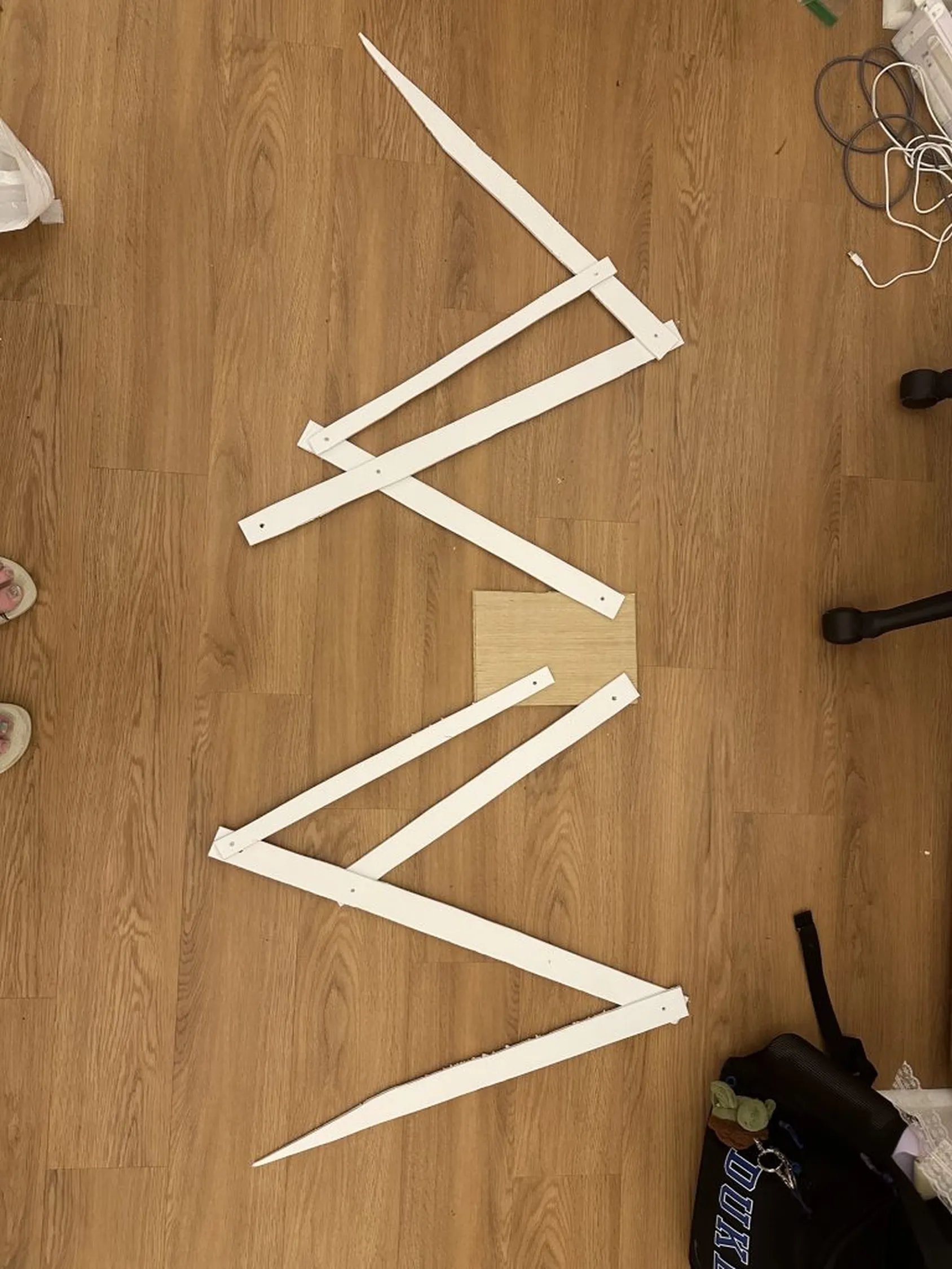
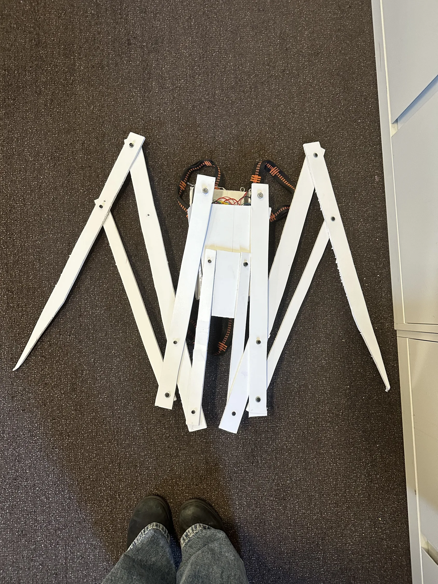
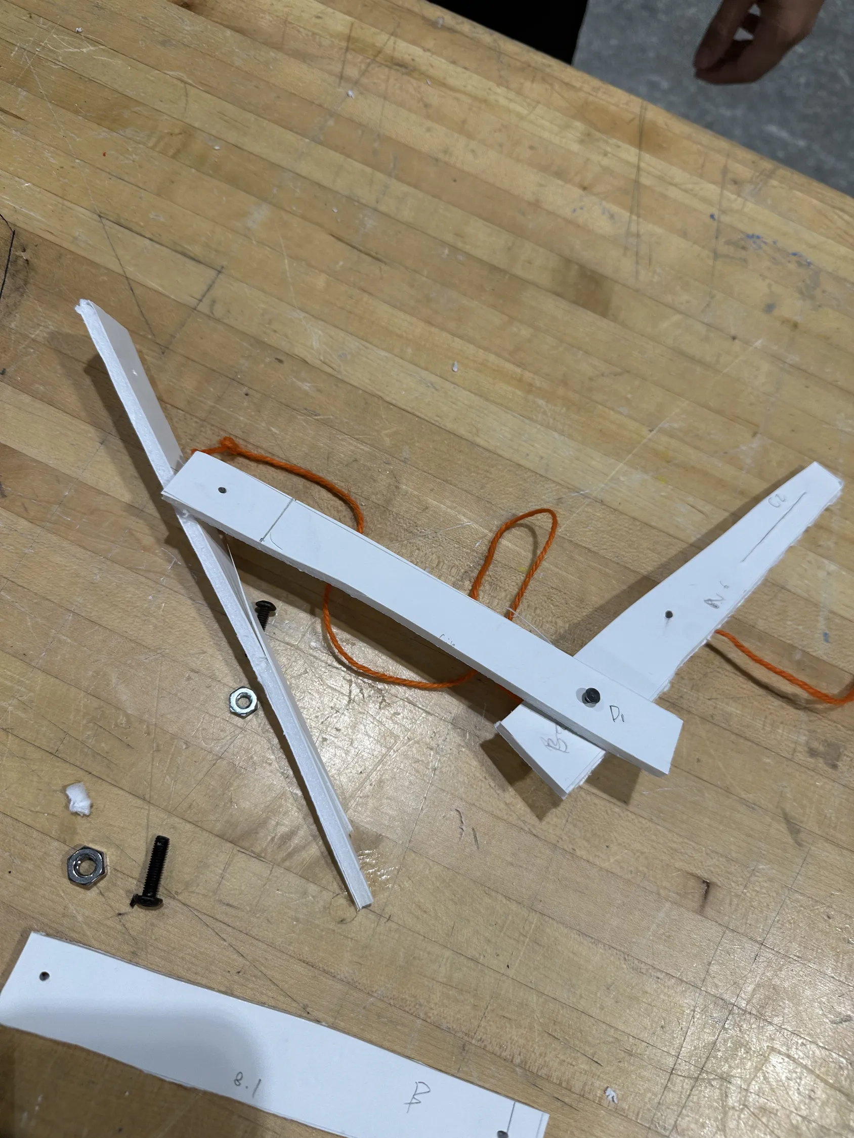
The structural framework of the wings was constructed from foam core, chosen as a lightweight, easily cut material suitable for quick iteration without requiring power tools. Each wing was assembled from a series of articulated segments fastened using bolts, washers, and screws, allowing the “bones” to pivot while remaining mechanically constrained.
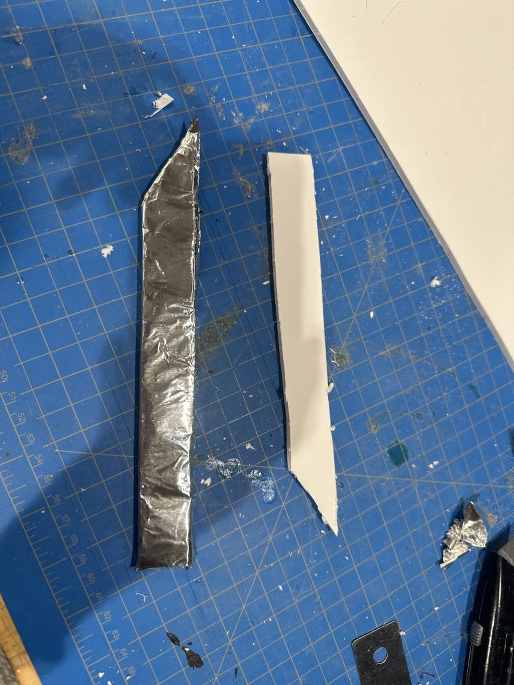
I developed one small-scale prototype followed by three full-scale versions. One version used aluminum sheeting to explore a more polished aesthetic; however, I ultimately reverted to foam core after observing interference with range of motion.
If extended, I would transition the structure to acrylic or lightweight composite materials to increase durability while maintaining low weight.
Technical Design
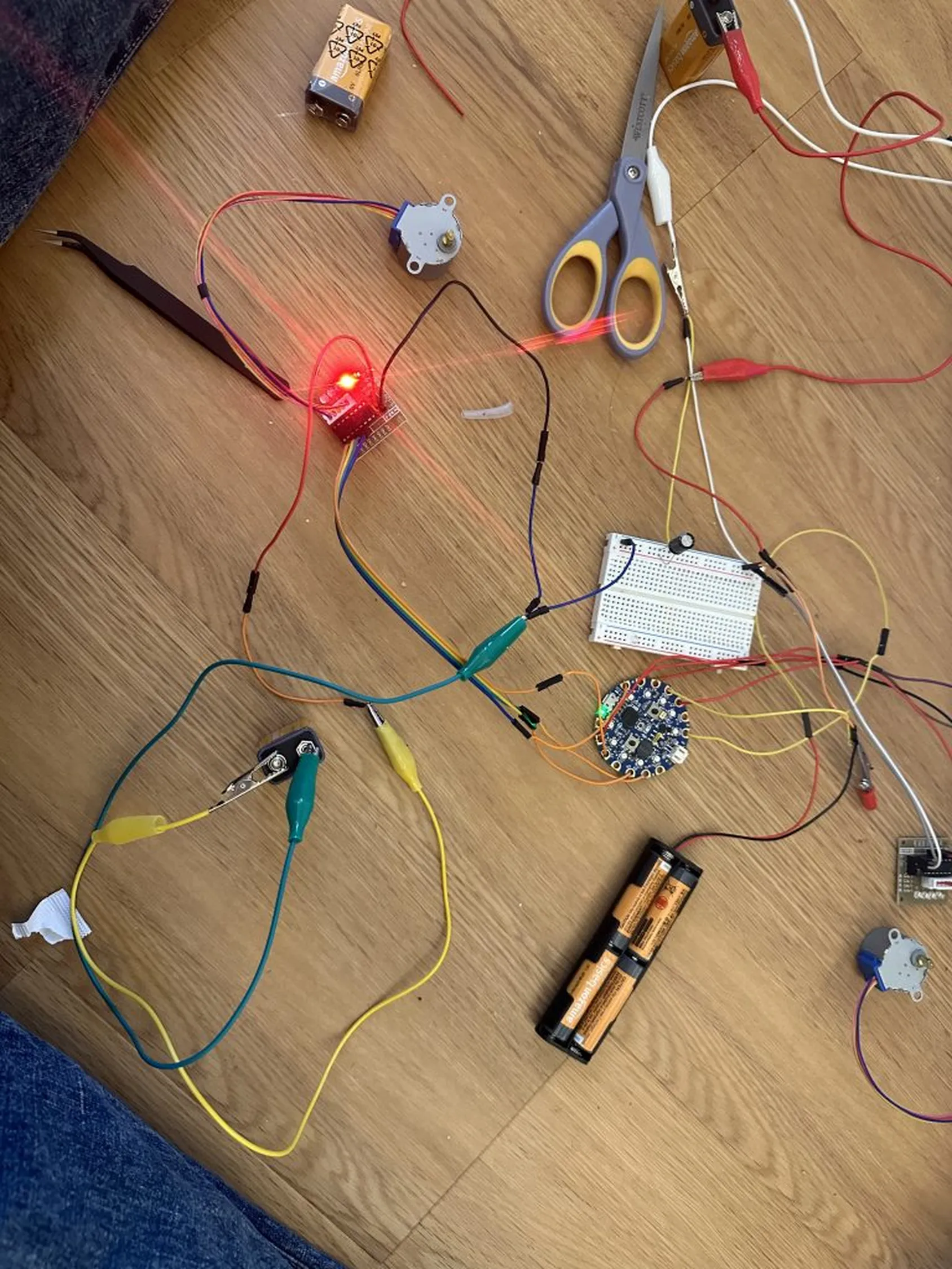
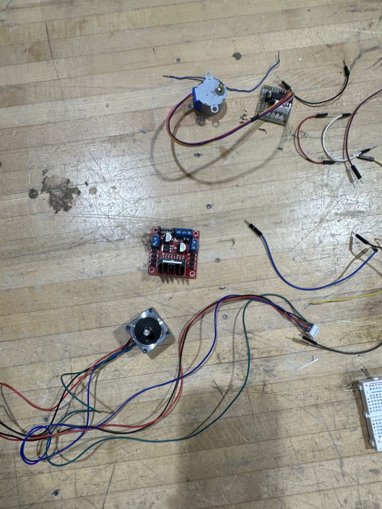
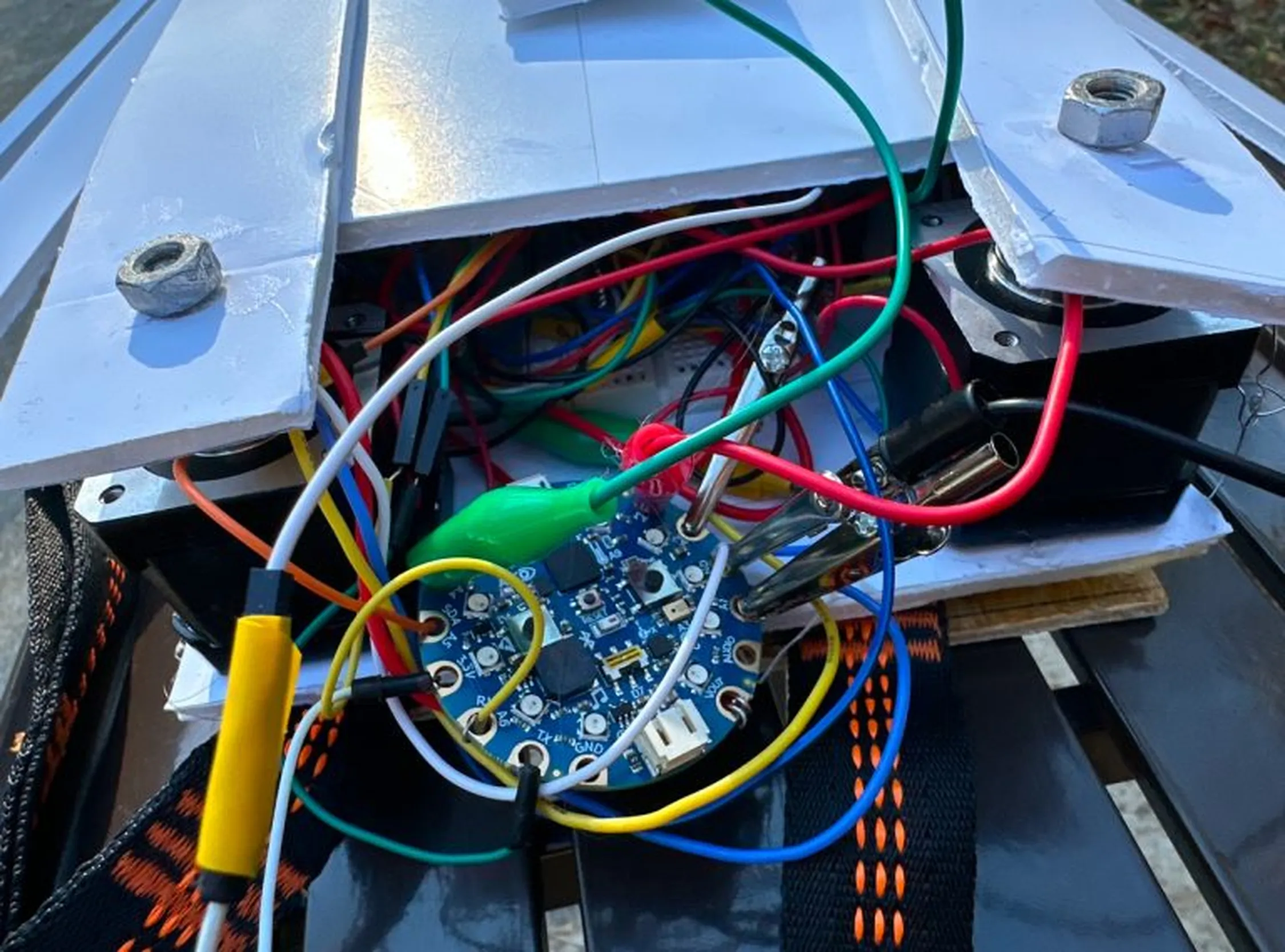
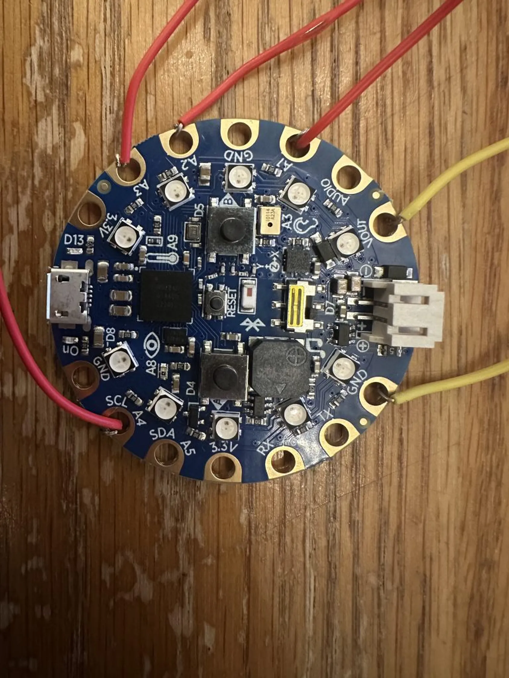
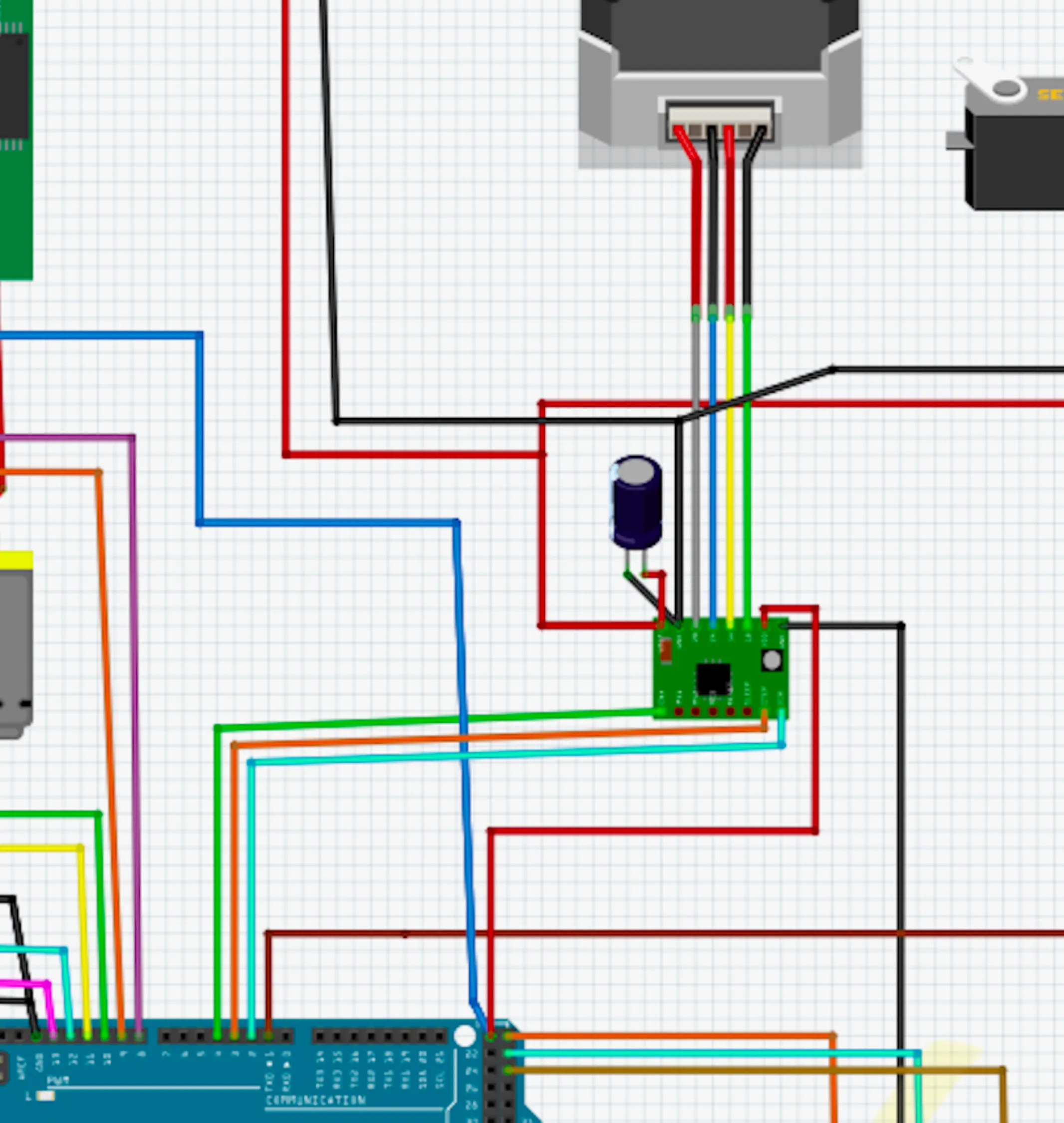
The motion-reactive wing system is built around the Adafruit Circuit Playground Bluefruit, which serves as both the microcontroller and the sensing hub. Its onboard accelerometer and motion sensors enable gesture-based control without needing additional hardware modules. The Bluefruit processes real-time motion data and outputs directional and PWM signals to two ROB-14450 motor drivers, which then drive the stepper motors connected to the wing segments. Programming for the microcontroller was done with python.
This architecture, separating logic-level control (3.3V) from motor power domains, follows standard embedded mechatronics design principles and allowed for rapid prototyping without specialized PCB fabrication.
Power System Considerations
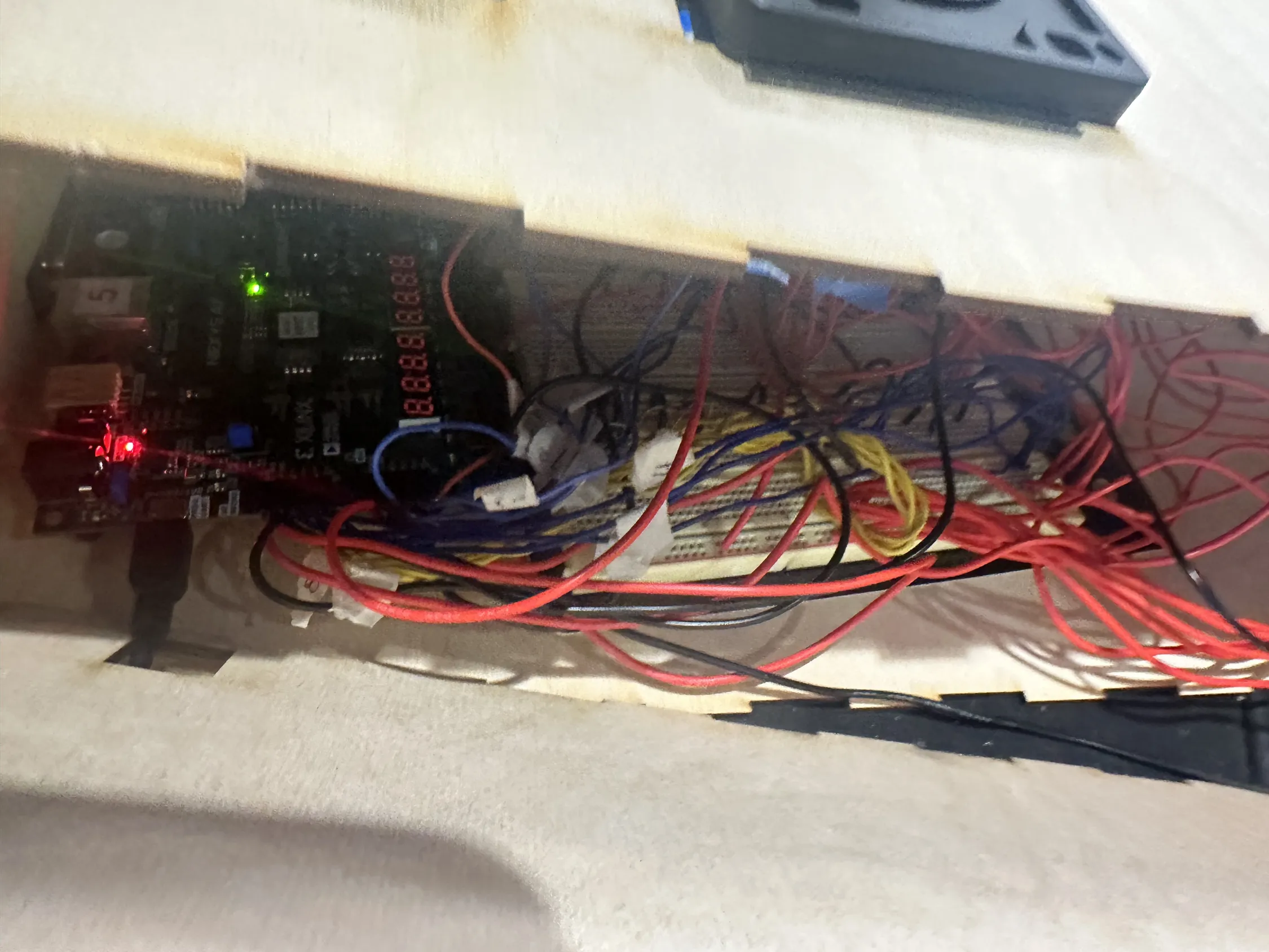
The prototype used three independent power supplies:
- A AAA battery pack for the Bluefruit
- Two separate high-voltage battery packs for each stepper motor
All supplies share a common ground on the breadboard to ensure consistent logic reference across drivers and microcontroller.
While this configuration is electrically valid for short-term experimentation, it has several engineering drawbacks:
- Voltage headroom: Alkaline 9V batteries in series can exceed the recommended VM voltage for both the motors and the driver ICs.
- Current delivery: 9V alkaline cells have high internal resistance and are not well-suited for sustained motor loads; voltage sag and heating are expected.
- Thermal behavior: Stepper drivers operating near their upper voltage limits risk thermal shutdown or component stress—consistent with some of the “near fire-alarm” moments during testing.
For future revisions, a single regulated LiPo battery pack (2S or 3S) with proper power distribution and fusing would provide a more stable, efficient, and safe power solution.
Motor Control and Driver Configuration
Each stepper motor is a bipolar 4-wire unit driven using both H-bridge channels of the ROB-14450 (TB6612FNG-style) driver. The wiring follows a standard configuration:
- Coil A → A01/A02
- Coil B → B01/B02
- Direction control via AIN1/AIN2 and BIN1/BIN2
- Speed/torque control via PWMA and PWMB PWM inputs
- STBY tied to a GPIO pin and held HIGH to enable the driver
This setup is appropriate for light to moderate loads. The foam-core wings were intentionally kept low-mass to stay within the torque limits of small steppers without additional gearing.
In a future iteration—especially with heavier materials such as acrylic—I would incorporate gear reduction, mechanical advantage, or higher-torque motors to ensure smooth articulation and reduced stall risk.
Wearable Integration
The custom backpack mount distributes load using cross-body straps fabricated from modified ratchet straps. This approach effectively reduces torque on the wearer and positions the motors near the shoulder line for optimal leverage.
Foam core was used for rapid iteration, but for long-term durability I would transition to laser-cut acrylic, lightweight composites, or aluminum linkages to improve rigidity while maintaining low weight.
Sensor and Control Logic
The Circuit Playground Bluefruit’s onboard accelerometer provides the motion-detection input. Gesture thresholds (e.g., tilt, acceleration spikes, or orientation changes) were mapped to wing articulation commands. The system performs well for expressive, directional motion cues, though more advanced filtering or IMU fusion would improve responsiveness.
In a future revision, I would explore:
- Kalman or complementary filtering for smoother motion inference
- More nuanced gesture classification
- BLE-based remote configuration or parameter tuning
Summary
Overall, the design is functionally valid and effective for a fast-paced physical computing prototype. While the electrical system would benefit from improved power distribution and more robust motor selection, the architecture demonstrates solid embedded-systems engineering and a clear understanding of mechanical–electrical integration.