A 1v1 real-time tank shooter game built from the ground up on a custom CPU designed in Verilog with a bespoke assembly language, running entirely on a Nexys A7 FPGA and outputting gameplay to VGA.
A 1v1 real-time tank shooter game built on a custom pipelined CPU designed in Verilog and programmed in a bespoke assembly language. Running on a Nexys A7 FPGA, the system manages all game logic — including sprite movement, bullet physics, collision detection, and health tracking — while rendering to a 640×480 VGA display. Players control tanks using arcade joysticks, competing in a custom-shaped arena until one player’s health reaches zero. The project integrates hardware design, low-level programming, and real-time graphics into a fully functional, hardware-driven multiplayer experience.
Fall 2024
1. Overall Project Design and Specifications
1.1 Project Objective and Core Features
The primary objective of the project was to create a real-time, multiplayer tank shooter game using the Nexys A7 FPGA which allows two players controlling tanks to navigate an arena, fire bullets, and attempt to deplete their opponent’s health. The core features include:
Real-time rendering on a 640x480 VGA display.
Tank and bullet movement based on joystick inputs.
Collision detection for bullets, tanks, and arena boundaries.
Real-time updates to player health and game state.
A custom arena (i.e., not just a square)
1.2 Sprite Movement
Sprite movement is handled by polling MMIO on each game tick. For each player, if an address in MMIO corresponding to the player’s movement controller is marked as active with a 0x1, we move the player’s sprite in that direction. We can separately move in both the x and y directions on each game tick, allowing sprites to move diagonally.
Each player’s sprite has their current x and y coordinates stored in SpriteRAM, which has its contents exposed as a 128-bit wire to the VGA Controller. The VGA controller then draws a 64x64 tank sprite for each player corresponding to the specified (x, y) position (which indicates the position of the top left pixel).
1.3 Bullet Mechanics
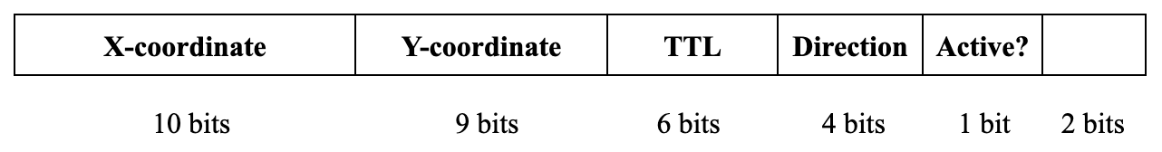
Bullets are the most critical gameplay element, and are implemented as 32-bit words using the following structure:
Here, the x-coordinate and y-coordinate represent the location of the bullet’s upper-left pixel. Bullets are 12x12 pixels in size and move across the screen up to 1 pixel in both the x and y directions on each game tick. The TTL does not actually represent the number of game ticks a bullet survives (as even the max of 64 game ticks is very short). Instead, these are intended to be customizable durations the bullet can last that are stretched out by a counter that only decrements the TTL every 20 game ticks. The direction is encoded as 4 bits of information that represents, UP, LEFT, RIGHT, and DOWN in that order. Diagonals can be encoded using a combination of these signals (i.e., UP-LEFT would be 1100). The active bit is used as an indicator for bullet processing, and it determines whether or not the bullet should be drawn onto the screen. To deactivate a bullet, we simply flip its active bit to 0. The final 2 bits are reserved as padding, and could potentially be used for future features (such as more extensive reflection logic).
Bullets are maintained throughout the duration of the game using a circular buffer containing 64 entries. We chose this data structure as we wanted some way to appear as though we could process an unlimited number of bullets, without exceeding limits of the BRAM on the Nexys A7 chip. Early on, we decided that we would only need a maximum of 64 bullets on screen at any point in time (and truthfully, we could have lowered this to 32 or even 16). As a result, when we wrap back around to the front of the circular buffer, we are guaranteed to be writing over a bullet that’s already been deactivated (and therefore, won’t disappear on screen).
On every game tick, we increment the (x, y) position of the bullet according to its direction, and on every 20th game tick, we decrement its TTL. A bullet with a TTL of 0 will have its active bit set to 0. However, as described below, a bullet may be marked inactive before it reaches this expiration in the case of a collision.
1.4 Collision Detection
Collision detection between bullets and sprites is necessary to determine whether or not a player has been hit by a bullet. Collision between the arena and players/bullets is mentioned separately below.
The bullet/sprite collision logic is handled in our bullet state loop that iterates over all bullets on screen. Essentially, when the (x, y) location of a bullet is updated, before we write the new location back to memory, we check to see if this new (x, y) position overlaps with either of the two sprites on screen. If there is an overlap, we set the bullet as inactive before saving the bullet back to BulletRAM and decrement the victim’s health.
1.5 Health Management
Each player maintains a health variable that starts at 100 and depletes after taking damage throughout the duration of the game. When a sprite is hit by a bullet, as determined by collision logic described above, the player’s health is decremented by 5, until one player’s health eventually reaches 0 and signals the end of the game.
Player health is stored in a dedicated memory region called HealthRAM which is exposed as an input to VGA Controller in a similar fashion to SpriteRAM. Each tank has an on-screen health indicator that updates in real time according to the player’s health stored in HealthRAM. The health image is drawn according to a large conditional block that checks for all possible health conditions (i.e., multiples of 5 from 0-100 since bullets each do 5 damage).
1.6 Arena Handling
Since we decided to have an arena that wasn’t just a square, we determined the boundaries of the arena using a list of pixels that correspond to the arena’s border. This ended up being one of the most significant challenges of the project and is described more in depth in the Challenges section of our report.
Essentially, at the beginning of the game, we load all pixels corresponding to the arena’s border into a region of memory called ArenaRAM. To handle collisions with sprites, we add a check to make sure that when we update a sprite’s location, we only save the new location if the new location doesn’t overlap with one of the arena’s border pixels. In order for this to work, we took a very minimal set of pixels needed to represent the arena’s border, but even this ended up being ~1250 pixels. This requires us to loop over this list of pixels for every sprite movement.
To handle collisions with bullets, our nesting logic becomes even more convoluted, but the minimal set of pixels we chose for our arena allowed us to avoid degrading performance. In the bullet state loop, we check each bullet against every pixel in the arena’s border. The only difference between this check and the check on the sprites is that if a bullet collides with the arena, we set the active bit to 0 instead of simply not allowing the movement. Overall, this nested loop iteration is the most computationally heavy aspect of our program as this requires 64 x 1025 x 4 = 262,400 checks on each game tick (64 bullets, 1025 border pixels, 4 directions to check).
2. Inputs and Outputs
The inputs/outputs of our project are relatively simple as our project was primarily software driven. Notably, the tanks have to be controlled somehow, and for this we opted for 8-direction joysticks which can be used to control sprite movement and bullet shooting. In total, we used four joysticks as digital input devices, one of which is used as directional controls for player movement and the other is used for shooting. These joysticks generate digital signals for each direction (UP, LEFT, RIGHT, DOWN), which are connected to pull-up circuits to ensure stable high signals when inactive. The pull-up configuration minimizes noise and provides consistent input detection for the system. We passed the outputs of these joysticks into the JC and JD ports on the Nexys A7.
For output, we interfaced the FPGA with a VGA display operating at a resolution of 640 pixels by 480 pixels. The VGA module generates synchronization signals for horizontal and vertical refresh, and the pixel data is mapped to a 12-bit color palette. We added a significant amount of Verilog to the VGA Controller to read in mem files so that we draw images that correspond with the current game state (determined by the contents of several memory regions).
3. Modifications to the Processor
Given that our project was nearly entirely software-based (excluding I/O from our arcade joysticks), we didn’t have a need to deviate far from our already working pipelined processor. While we didn't add any custom instructions to complete our project, we did incorporate a number of new memory regions as both a logical separation of game elements and as an easy way to direct wires relevant to game logic directly into our VGA Controller.
New Memory Regions Added:
SpriteRAM: Stores (x, y) positions of both sprites on screen which represent the top left pixel.
BulletRAM: Each bullet's data, including its position, direction, TTL, and active state, is stored in a dedicated memory module which is passed to the VGA Controller to draw 12x12 red bullets for all addresses marked with an active bit.
HealthRAM: Health values for both players are stored in a small, dedicated memory block and passed to VGA Controller, which outputs an image to represent the player’s health based on a large conditional block.
ArenaRAM: Preloaded data defining the static elements of the arena, such as boundaries (and obstacles in the future). The memory is read during collision checks to ensure accurate interactions between sprites and bullets with the arena.
MMIO: Fed the raw JC and JD ports from the FPGA’s input but otherwise is read-only. Each address corresponds to an active bit for a different input (i.e., player1controller1_left, player1controller2_up, etc.)
4. Challenges and Solutions
This project has by far been one of the most complex assignments either of us has ever tried to tackle, and as a result we faced roadblocks along the way. For the scope of this report, there are three main challenges that we’ll focus on.
4.1 The “Zero-to-One” Problem
When starting our project, we had a number of things we weren’t sure worked properly and as a result, we weren’t sure how to even begin testing our modifications. For example, we wanted a new region of memory to handle bullets, but we didn’t know whether or not this was being written to correctly. Furthermore, we didn’t know whether or not it was being correctly read and updated by the VGA controller. Lastly, the bullets were only populated after seeing some input from MMIO, and we weren’t even sure whether the MMIO was being handled properly or if it would actually update the BulletRAM. We found that many of these things were difficult to test since Verilog verification files we were used to testing with didn’t work with either our joystick inputs or VGA outputs.
To solve this, we developed a plan to test the most minimal aspect of each of these components. First, we wrote verification files to ensure that the new BulletRAM was being written to properly, and we also tested that writing to normal RAM would not overwrite this. Here, we found out that the write to normal RAM actually did overwrite the write to BulletRAM since we hadn’t handled the mux to address the new region properly, and as a result we were simply taking the lower bits of the new memory address and writing to normal RAM at that location.
Next, we tried hard-coding a .mem file which we passed into BulletRAM to ensure that regardless of whether our MMIO was working, we could have contents in BulletRAM. We used this to ensure that if BulletRAM was written to, we could draw it correctly in the VGA Controller. This helped us find where to insert this new “draw bullet” logic.
Lastly, we tried hooking all this up and trying to get the pixel to display after writing to MMIO using one of the joystick inputs. This helped us address mistakes in our physical wiring of the controllers, and eventually allowed us to test the original end-to-end workflow of generating a bullet on screen after asserting some input.
4.2 Bullet Handling
“How to handle bullets” was the core design problem that we had difficulty with as we originally weren’t sure how we would display a variable number of bullets on screen. As mentioned earlier, we ended up going with a circular buffer solution that updates the active state of each bullet on every game tick.
Our problems didn’t end here, however, as once the bullets were able to fire, we noticed that a large amount of bullets would spawn on each joystick input, even though we had only intended to poll for one possible bullet fire on each game tick. We realized later that this was because after polling MMIO once, we mistakenly jumped back to the top of the MMIO loop to attempt to poll MMIO again, which would keep us in a cycle until the player released the joystick. However, even after this, firing on each game tick created issues, so we implemented cooldown logic to prevent players from firing too fast. When a bullet is fired, the player that shot the bullet has their cooldown set to 100 game ticks (written to an address in normal RAM). This cooldown is decremented on each game tick until it reaches 0, and when a player attempts to shoot a bullet, we first run a check to make sure their cooldown is equal to 0; otherwise we won’t fire the bullet.
Bullets also highlighted another core issue with our game, which was that our arena was not generating bounds perfectly (even though they appeared as if they were sprites). Since our bullets were originally smaller, they glitched through small gaps in our border, highlighting another issue with our game (described as the next challenge below).
4.3 Arena Collisions
Our original arena simply covered a rough line of pixels generated by drawing around our arena’s border in Photoshop. This rough border appeared to work originally, so we kept developing our project, but once we developed bullet collision logic, we started to notice problems with the arena and decided to test more extensively.
Essentially, to generate the arena’s border, we created a Python script that could read in a version of the arena consisting of red pixels for the border, and white pixels for all other pixels. This allowed us to very quickly generate a mem file to represent our arena.
On the right is the version of this that works correctly, however we originally ran into issues with the version of this in Photoshop due to anti-aliasing. This caused one of two issues to appear depending on the level of sensitivity we had for what determined whether a pixel was red (i.e., whether a red pixel needed to have color.r = 255, or if simply not being a white pixel was enough). Firstly, if we were too liberal with what was considered a red pixel, the anti-aliasing would cause some “pockets” of pixels to appear, which allowed a sprite to get stuck in the border if it used a diagonal direction, and it would not be able to free itself using non-diagonal directions. We don’t have any pictures of this version of the project, but the diagram on the right portrays the behavior we observed. When going the other direction (i.e., too strictWith what we considered a red pixel), we noticed that our bullets (when they were originally 4x4 pixels) were able to glitch through the border if they were unlucky enough to hit an edge right on its dead pixels.
Ultimately, we were able to fix both of these issues by disabling anti-aliasing and manually ensuring that the 1px line around the pentagon perfectly aligned with what we were going for. After running our Python tool on this version of the red pentagon, we no longer saw these issues.
5. Testing Plan and Results
We used testing plans throughout the project to ensure that even our minimal changes aligned with our expectations. This included both regression tests to ensure previously functioning components remained functional, and integration tests to properly roll out new features. One such example is when we implemented bullet collision logic and found that bullets never appeared to spawn anymore because their default location was the center of the sprite that shot it. This was fixed by setting each bullet to spawn at an offset from the sprite in the direction it was headed.
After implementing all features for our project, we performed a number of checks to make sure that each feature worked as intended.
5.1 Unit Tests
Below are each of the tests we ran after implementing all features to ensure that everything worked properly:
Bullets spawn at the correct offset according to direction.
Bullets continue to move in the direction they are shot
Bullets are set to inactive upon contact with a sprite
Bullets are set to inactive upon contact with the arena
An unlimited number of bullets can be shot (test by wrapping around to front of the circular buffer with 65 bullets)
A player’s health is decremented by 5 after their sprite is hit by a bullet
Sprites spawn in at the expected locations on screen
Sprites cannot exceed the bounds of the area in any direction
Players cannot instantly shoot bullets after each other—a cooldown prevents them from doing so
Upon a player’s health reaching zero, their sprite is set to inactive and is no longer drawn on screen
Upon a player’s health reaching zero, the game freezes temporarily, indicating the end of the game
5.2 Testing Results
After implementing all features in our project, we passed nearly every one of our unit tests we set for ourselves which we attribute to rigorous testing throughout the project. Interestingly though, we failed the “65 bullets” test but only sometimes. Basically, what would happen is that only sometimes when we tested it, the 65th bullet shot would appear on screen, but never move. After some investigation, we found that it was only player 2 that had this issue. Upon inspecting the assembly, we found this was because we forgot the assembly instruction to reset the pointer to the next available bullet position in a circular buffer manner for player 2. After fixing this, we no longer saw this issue.
6. Assembly Program Walkthrough
Our assembly project consists of ~1250 instructions (~600-700 of these being meaningful) which handles sprite movement, collision detection, and maintenance of bullet state via a circular buffer. The core execution loop of our program works as such:
6.1 Game Initialization (Memory Regions, Load Health): The program begins by setting up memory regions for sprites, bullets, and player health. Initial values for health and position are loaded into their respective memory addresses, ensuring the game starts in a consistent state.
6.2 Update Shooting Cooldowns: Before processing inputs, the program updates cooldown values for each player's shooting mechanics. This prevents players from spamming shots (an overpowered mechanic, from our testing).
6.3 Movement Processing (Poll MMIO): Inputs from the four joysticks are polled through MMIO registers. Based on these inputs, the program calculates potential new positions for sprites and applies these movements, pending collision checks.
6.4 Shooting Processing (Again, Poll MMIO): The program again polls the MMIO registers, this time for shooting inputs. If a valid shooting action is detected and the cooldown has expired, a new bullet is added to the circular buffer with its initial position and direction.
6.5 Update Bullet State: The program iterates through the circular buffer of bullets, updating their position based on their direction, decrementing their TTL, and deactivating bullets if their TTL reaches zero.
6.6 Check for Arena Collision: Each sprite and bullet's position is checked against the arena boundaries and static obstacles, ensuring that objects stay within playable limits and interact realistically with the environment.
6.7 Check for Sprite Collision: Collisions between sprites and bullets are detected in this step. If a bullet overlaps with a sprite, the active flag for the bullet is cleared.
6.8 Decrement Health if Necessary: When a collision is detected, the health of the impacted sprite is decremented. If health reaches zero, the game transitions to a reset state, and the program reinitializes for a new game loop.
7. Future Improvements
While we implemented almost all the features we set out for ourselves, there were a couple of interesting add-ons we thought of during the project that could have been fun to explore:
7.1 Dynamic Arena Elements: Dynamic obstacles, such as moving walls or destructible barriers, could add some fun complexity to the gameplay. Since we already manage the arena with dedicated space in RAM, we could periodically update the arena memory to reflect changes that we introduce. We also thought the introduction of some “portal” mechanic, where you can have bullets teleport between portals, could be cool.
7.2 Sound Integration: Incorporating sound effects for actions like shooting, collisions, and game-over events could further improve the cohesiveness of our project. Since we already spent a lot of time on branding our game and creating dedicated graphics, making custom sounds for the game could give it a much more immersive feel.
7.3 Reflection Collision Logic: Originally, we wanted to implement some form of reflection logic to allow complex strategies like bounce shots (this is why we added a TTL field to the bullets after all). We did try implementing a simple version of reflection logic that simply reversed a bullet’s x or y coordinate depending on the direction it hit a border, but ultimately this looked strange visually (i.e., a bullet would reflect sideways off a diagonal wall). For proper collision logic, we would attempt to detect collisions separately for the four corner pixels of each bullet to determine which direction it should bounce.
7.4 More Game Screens—SD Card/Compression: Towards the end of the project, we ran into issues with the amount of BRAM and LUT storage available on the FPGA. This was super unfortunate, as we spent lots of time creating custom screens that tie in with the game’s theme, but were unable to actually include them in the project (feel free to take a look at these in our Project Graphics Library). We would’ve loved to explore options to expand the FPGA’s storage capacity in order to include these in our finished product.